


Interpreting electrical blueprints may seem daunting, but fear not – mastering this skill is within your reach. Understanding how to read electrical blueprints is like deciphering a complex yet fascinating puzzle. Each line, symbol, and annotation holds a crucial piece of information waiting to be decoded. So, let’s embark on this journey together, as we unravel the secrets hidden within these intricate diagrams. Let’s dive right in and demystify the world of electrical blueprints.

Unlocking the Mystery: How to Read Electrical Blueprints
Welcome, aspiring electricians and DIY enthusiasts alike! Have you ever looked at an electrical blueprint and felt like you were trying to decipher a secret code? Fear not! In this comprehensive guide, we will break down the intricacies of reading electrical blueprints in a way that is easy to understand and apply. By the end of this article, you will feel confident in your ability to navigate through these essential documents with ease.
The Basics of Electrical Blueprints
Before we dive into the specifics, let’s start with the basics. Electrical blueprints are detailed drawings that outline the electrical wiring and systems in a building or structure. These blueprints are essential for electricians, engineers, and construction professionals to understand how the electrical components of a building are laid out and connected.
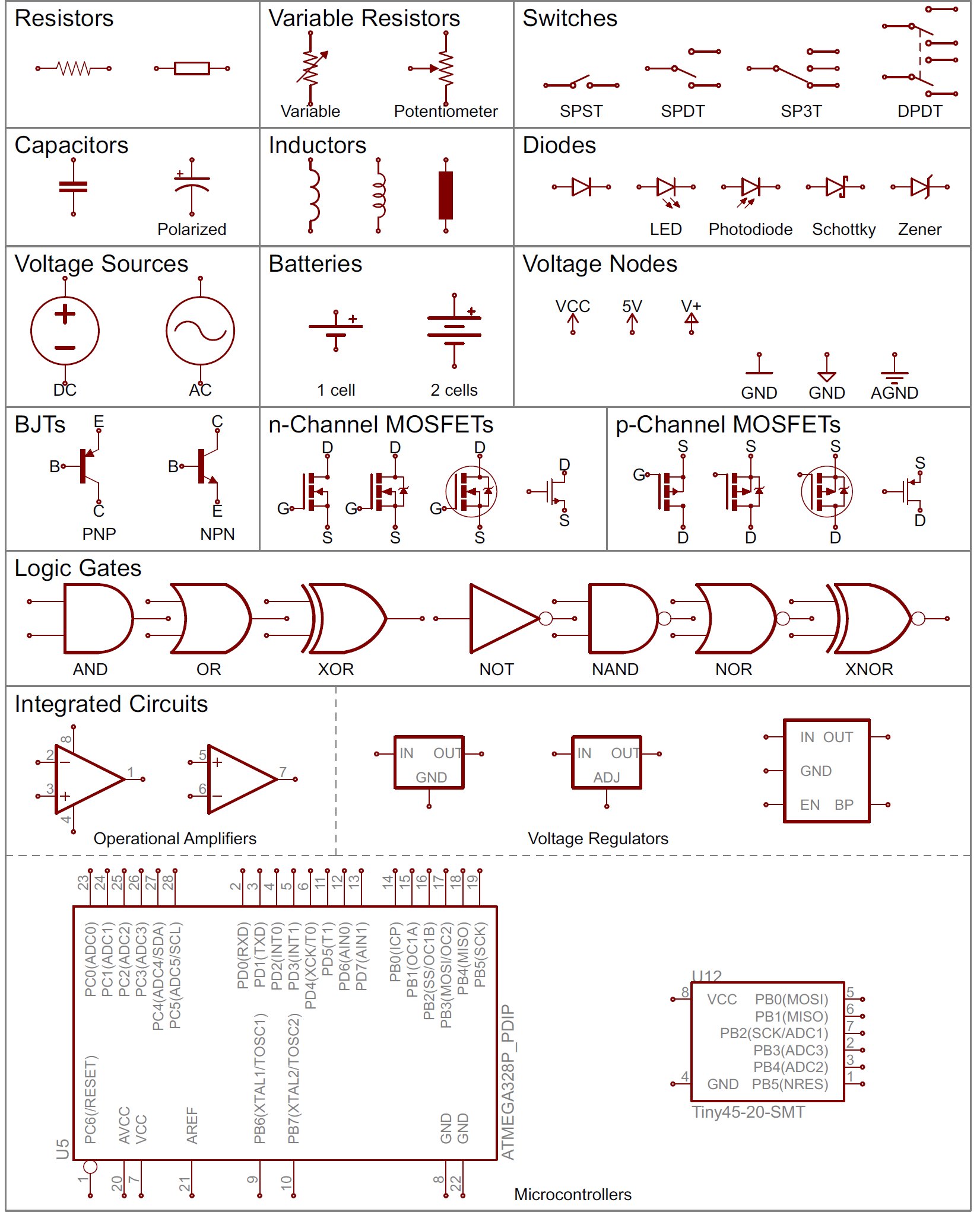
Understanding Symbols and Abbreviations
One of the first things you’ll notice when looking at an electrical blueprint is the abundance of symbols and abbreviations. These symbols represent various electrical components, such as outlets, switches, lights, and circuits. It’s important to familiarize yourself with these symbols to make sense of the blueprint.
For example, a circle with a cross inside typically represents a light fixture, while a zigzag line indicates an electrical receptacle or outlet. Take the time to study common electrical symbols and their meanings to better interpret the blueprint in front of you.
Reading Circuit Diagrams
Circuit diagrams are a vital part of electrical blueprints as they show how electrical components are connected in a circuit. Understanding circuit diagrams is crucial for troubleshooting issues and ensuring that the electrical system functions correctly.
When reading a circuit diagram, follow the flow of the electrical current from the power source through the components and back to the source. Pay attention to how the components are connected, including the type of wiring used and any junctions or connections along the way.
Interpreting Floor Plans
Another essential aspect of reading electrical blueprints is interpreting floor plans. Floor plans show the layout of a building, including the placement of walls, doors, windows, and electrical components. Understanding how to read floor plans will help you visualize how the electrical system fits into the overall structure.
Identifying Electrical Zones
When examining a floor plan, look for areas designated for specific electrical zones, such as the kitchen, bathrooms, or living spaces. Each zone will have its own set of electrical requirements, including the number of outlets, lighting fixtures, and switches needed to meet safety and functionality standards.
By identifying these zones on the floor plan, you can better understand how the electrical system is distributed throughout the building and ensure that each area is properly equipped with the necessary components.
Following Electrical Pathways
Electrical blueprints also include information about the pathways that electrical wiring will follow throughout the building. These pathways may be shown using symbols or annotations that indicate where the wiring is routed, such as through walls, ceilings, or conduits.
By following the electrical pathways on the blueprint, you can track the flow of electricity from the main power source to individual components, ensuring that the wiring is installed correctly and safely within the building structure.
Examining Panel Schedules
Panel schedules are another crucial element of electrical blueprints that provide detailed information about the electrical panels and circuits in a building. These schedules outline the distribution of power throughout the building and help electricians identify specific circuits and their corresponding components.
Understanding Load Calculations
One of the key aspects of a panel schedule is load calculations, which determine the electrical load that each circuit can handle without overloading. By reviewing the load calculations on the panel schedule, electricians can ensure that the electrical system is balanced and that circuits are not being overloaded, which can lead to safety hazards.
Pay close attention to the load calculations for each circuit on the panel schedule to ensure that the electrical system is designed to handle the power requirements of the building without exceeding its capacity.
Tracking Circuit Numbers
In addition to load calculations, panel schedules also include circuit numbers that correspond to specific electrical components or areas within the building. These circuit numbers help electricians identify and trace circuits throughout the building, making it easier to troubleshoot issues and make modifications as needed.
When examining a panel schedule, make note of the circuit numbers and their corresponding components to create a clear map of the electrical system and ensure that all circuits are properly labeled and accounted for.
Congratulations! You have now unlocked the secrets of reading electrical blueprints. By understanding the symbols, circuit diagrams, floor plans, panel schedules, and other elements of electrical blueprints, you are well on your way to becoming a master at interpreting these essential documents.
Remember, practice makes perfect, so don’t be afraid to dive into real-world electrical blueprints and test your newfound knowledge. With perseverance and a keen eye for detail, you’ll soon be navigating through electrical blueprints with confidence and ease. Happy reading!
Blueprints Deciphered: How to Read Commercial Plans (For Electricians)
Frequently Asked Questions
What information is typically displayed on electrical blueprints?
Electrical blueprints usually contain information about the location of electrical outlets, switches, lighting fixtures, and other components. They also show the wiring connections, circuitry, and any additional electrical systems present in a building.
Why is it important to know how to read electrical blueprints?
Understanding electrical blueprints is crucial for electricians, engineers, and other professionals in the construction industry to accurately implement electrical systems. It helps ensure that installations meet safety standards, regulations, and design specifications.
How can one identify different symbols and abbreviations on electrical blueprints?
To interpret symbols and abbreviations on electrical blueprints, one can refer to the legend or key provided on the blueprint. This key explains the meaning of each symbol or abbreviation used, making it easier to understand the layout and connections represented.
What are some common mistakes to avoid when reading electrical blueprints?
Common mistakes to avoid when reading electrical blueprints include misinterpreting symbols, overlooking important details, or neglecting to follow the flow of circuits correctly. It’s essential to pay attention to scale, direction, and labels to avoid errors in implementation.
Final Thoughts
In conclusion, understanding electrical blueprints is crucial for professionals in the field. By familiarizing yourself with symbols, scales, and electrical plans, you can effectively interpret and implement these designs. Remember to pay attention to labels, legends, and notes for clarity. Practice reading electrical blueprints to hone your skills and boost your confidence in working with electrical systems. Mastering how to read electrical blueprints will enhance your proficiency and efficiency in the industry.